Specifications
| Symbol | Parameter | Condition | Minimum | Typical | Maximum | Unit |
|---|---|---|---|---|---|---|
| P | Operating Pressure | – | -110 | – | -200 | Pa |
| Rload | Output Load | – | – | 0.8 | – | Ω |
| Vdd | Operating Voltage Range | – | 2.1 | – | 5.0 | V |
| Iq | Static Current | – | – | 3 | 5 | uA |
| RDS(ON) | Discharge Path On-Resistance | VDD=3.7V | – | 50 | – | mΩ |
| ILED | LED Current to Ground | 2.7V≤VDD≤4.1V | – | 4.2 | – | mA |
| ICHARGE | Charging Current | 2.7V≤VDD≤4.1V VDD≤2.7V |
– – |
550 70 |
– – |
mA mA |
| TSD | Over-Temperature Protection Threshold | During Charging During Discharging |
75 140 |
85 150 |
95 160 |
℃ ℃ |
Key Features
- Patented MEMS Chip
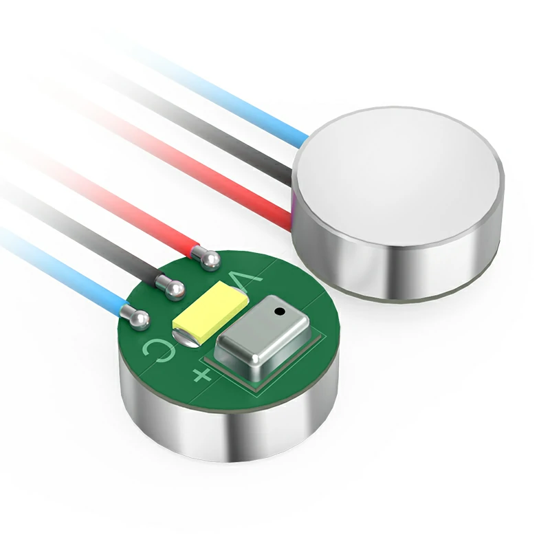
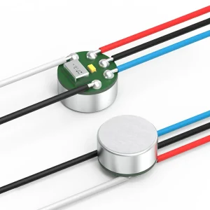
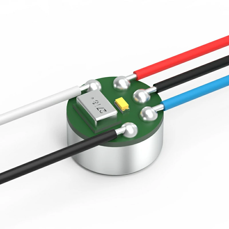
KOOM’s MEMS airflow sensor features excellent consistency in trigger pressure and is not affected by oil vapor.
It is produced using semiconductor microfabrication, making it resistant to oil corrosion. Its unique patented design of the MEMS structure allows it to function normally even after being immersed in oil for up to 7 days. The capacitance value has a wide range of variation between open and closed states, providing excellent fault tolerance. This sensor is suitable for large-scale automated production because it is a semiconductor device, making it highly compatible with SMT (Surface Mount Technology) for large-scale automated production.
Furthermore, it has undergone the industry’s longest reliability verification with 100,000 switch cycles, maintaining a start-up pressure within +/- 15 Pa, ensuring an extended lifespan and excellent stability.
Through repeated validation and testing, this sensor has a self-purging function and can withstand at least 50 backflush operations. We employ professional chip design and utilize a PWM (Pulse Width Modulation) module to control LED lights for indicating the operational status.
- Safety Module
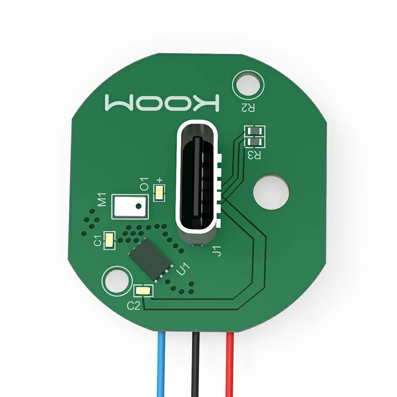
The internal integrated charging control circuit supports multiple charging modes, including trickle charging, constant current, and constant voltage charging processes, providing superior charging performance.
Additionally, it has battery protection functionality. When the lithium battery voltage drops below 2.7V, it switches to trickle charging mode to protect the battery. When the battery voltage exceeds 2.7V, it initiates high-current charging, and as the battery voltage approaches 4.2V, the charging current gradually decreases, entering the constant voltage charging mode until charging is stopped at 4.2V.
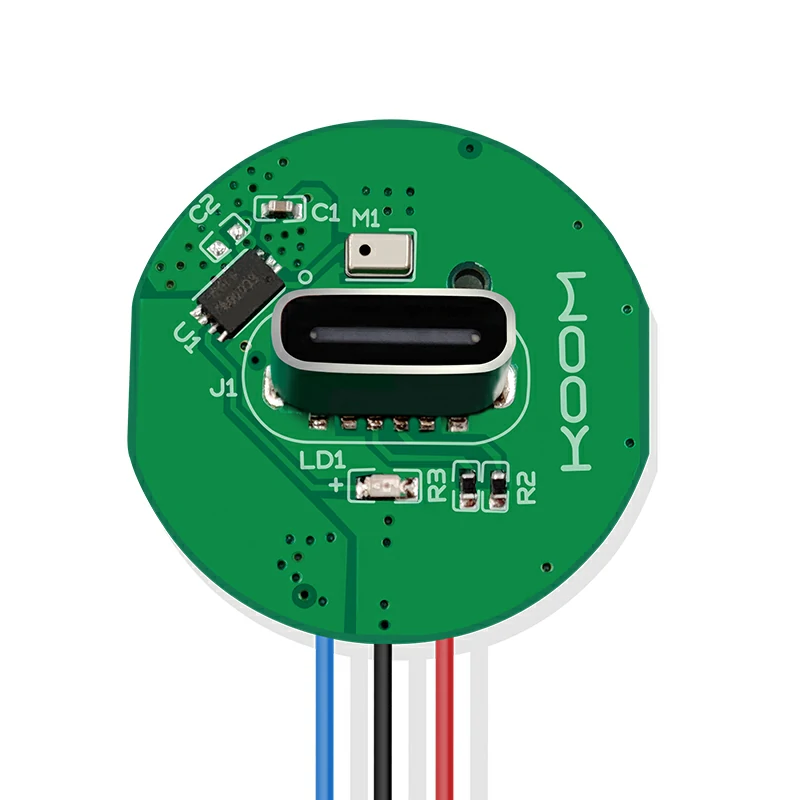
This circuit also supports various AC-DC and USB charging devices, including TYPE-C.
- Protection Module
This module includes an undervoltage lockout module (UVLO), over-temperature protection module (OTP), control module for AT drive port overcurrent protection, short-circuit protection (SCP), and lithium battery protection module. It also provides features such as long-term smoking protection and charging over-temperature protection to ensure the safety of the device and the user.。
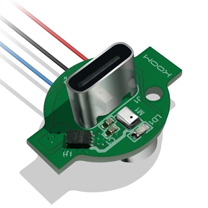
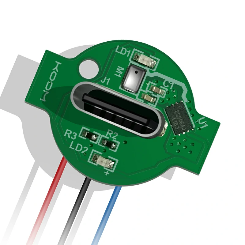
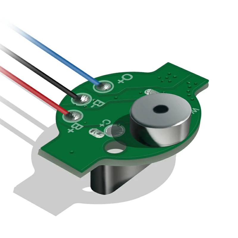
Hardware Architecture
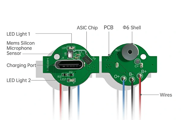
Key Material Advantages
| Material Names | Features |
|---|---|
|
Electronic Cigarette ASIC Chip |
Independently developed ASIC with powerful performance and high cost-effectiveness, widely used by renowned top brands. |
|
Electronic Cigarette MEMS Sensor |
Self-developed reverse-logic MEMS with multiple patented technologies, exhibiting excellent performance. It has good resistance to oil and corrosion, allowing it to fully leverage product capabilities. |
Frequently Asked Questions
- What capacitor is used in an electronic cigarette atomizer?
Capacitors are typically not used in the atomizer of an electronic cigarette. They are commonly used in the electronic cigarette’s circuit board (PCBA) or battery management system to store charge or smooth voltage in the circuit, supporting the normal operation of the electronic cigarette device. The type and specifications of capacitors are chosen based on the specific electronic cigarette design and functionality, rather than being part of the atomizer.
- How is an electronic cigarette atomizer used?
The atomizer of an electronic cigarette is a component used for inhaling vapor and triggering the electronic cigarette device. The general steps for usage are as follows: Install the atomizer, check the electronic cigarette’s status, inhale, monitor the vaping operation, exhale, monitor the electronic cigarette’s status, and end the vaping session.
- What is the soldering process for an electronic cigarette control board?
The general steps for soldering an electronic cigarette control board are as follows: Prepare the work area, inspect the control board, solder components, solder connectors, use solder paste, inspect soldering quality, remove soldering residue, and test the circuit. Please note that if you lack soldering and electronic assembly experience, it is advisable to seek professional assistance from us.

Reviews
There are no reviews yet.